This website uses cookies to ensure you get the best experience on our website. Read our cookie policy


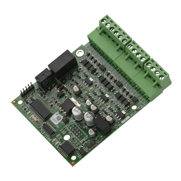
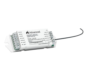
Advanced MXP-532 MxPro 5 Routing / Protection Interface
SKU
MXP-532
£257.90 £214.92
Advanced MXP-532 MxPro 5 Routing / Protection Interface
The Advanced MXP-532 General Routing Interface Card is an optional module to provide fire routing outputs compliant with BS EN54-2: 1998 Clauses 7.9 and 8.9 and BS5839-1:2002.
This module provides monitored circuits to either fire/fault routing equipment or fire protection equipment.
Applications / Limitations
EN54-2 compliant routing interfaces providing monitored outputs to the fire alarm and routing circuits. Circuits are monitored for open and short circuit conditions in both normal and active mode - compliance with EN54-2 and BS5839-1: 2002 Clause 12.2.1a.
The outputs will drive relay coils with impedances of between
1kΩ and 5kΩ.
Compatibility
Can be used with all MxPro 5 series control panels programmed with version 50.07 software or later, compatible with the
PC-Configuration tool from version 6.12 or later. The interface connects directly to peripheral bus connection in the panel.
| Key Features |
|---|
| > Two fire routing outputs are provided to differentiate between Call Point (MCP) and Automatic Detector (AFD) fire alarm signals if required > Outputs are monitored for open and short circuit wiring issues in both the quiescent and active states, and fault conditions reported on the panel (CIE) display/LED Indicators > Outputs are compatible with a wide range of routing equipment > Simple to install and configure > Monitored outputs > Wide range compatibility |
| Manufacturer | Advanced Electronics |
|---|---|
| MPN | MXP-532 |
Write Your Own Review

Sort By:
No questions yet. Be the first to ask the question!
| Output Circuit Spec. | 24V DC active, 5V DC monitor |
| Fire & Fault Outputs | 1.0mA monitor mode nominal, 5.0mA-25.0mA active (energised) mode dependent upon coil impendence, 40.0mA maximum short circuit. |
| Input Circuit Spec. | 4x Monitored Input - EOL 10KΩ, operating resistor 470Ω |
| Operating Voltage | 24V DC [Range 19-28V] from panel auxiliary Supply Output. |
| Panel Loading, standby, AC Mains fail (fault output off) | 43mA |
| Panel Loading, quiescent state (fault output on) | 45mA +24mA (1KΩ coil), +5mA (5KΩ coil) |
| Panel Loading, ALL inputs and outputs active | 48mA +72mA (1KΩ coils), +15mA (5kΩ coils) |
| On-board indications | 6x LED indicators for outputs active, communications and microprocessor heartbeat |
| Operating Temperature | 0°C to 50°C |
| Approvals | BS EN54-2: 1998 |
More from Advanced Electronics